Linker scripts
March 11, 2019
I while ago I wrote a post about linking basics, where I talked about ELF files and their structure. This post is based on chapter 7 from the book Computer Systems: A Programmer’s Perspective and this document
Object files
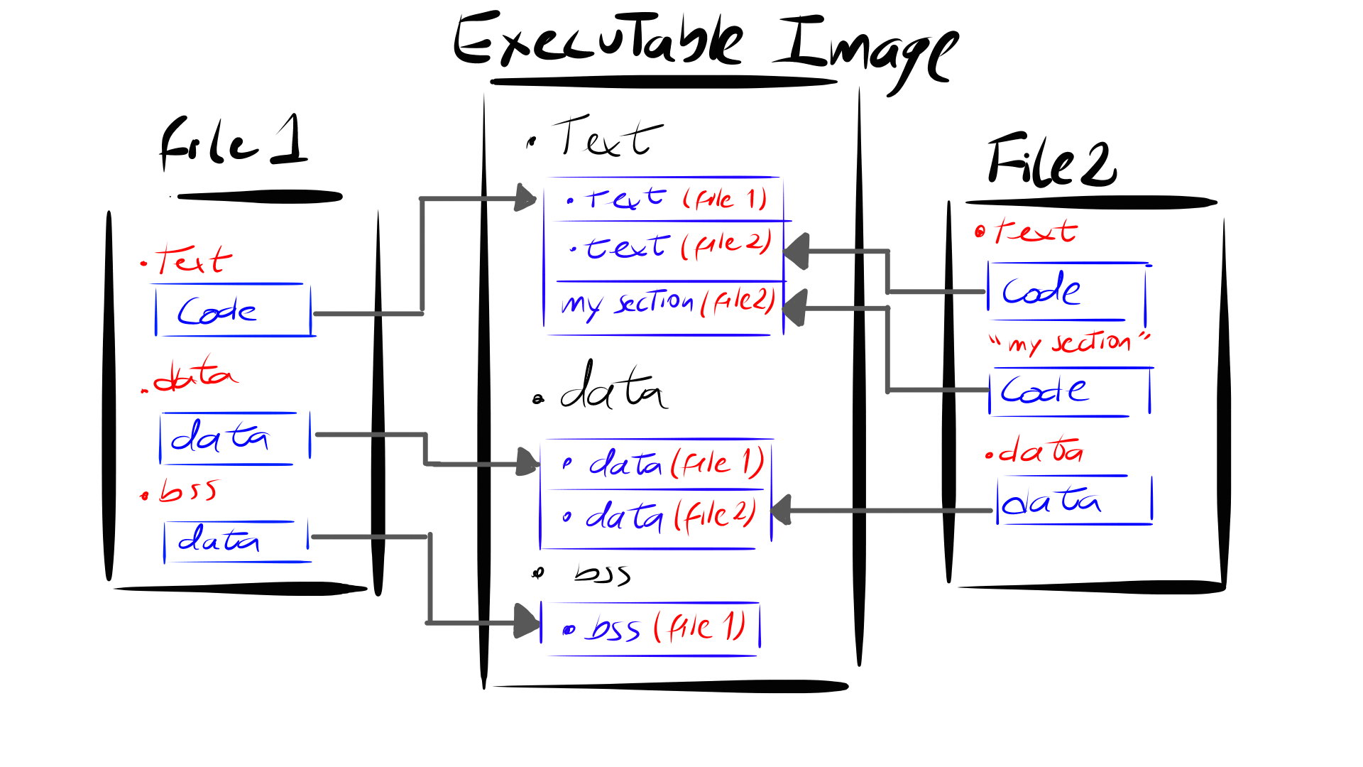
Linkers combines inputs files (relocatable files) into a single output file (executable file), this files are object files
Object files come in three forms:
- Relocatable object file. Contains binary code and data in a form that can be combined with other relocatable object files at compile time to create an executable object file.
- Executable object file. Contains binary code and data in a form that can be copied directly into memory and executed.
- Shared object file. A special type of relocatable object file that can be loaded into memory and linked dynamically, at either load time or run time.
Each object file has a list of sections:
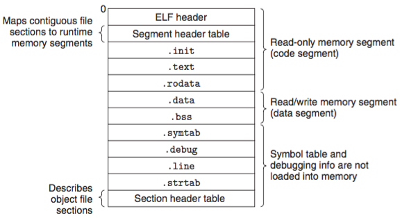 Image obtained from this site
.initis the initialization code before themainin C such as set to zero global variables or defined the interrupt vector table..textis the machine code of the compiled program.rodataread-only data, such asconst char.dataglobal variables that have been initialized.bssuninitialized global variables.symtabtable symbol with information about functions and global variables that are defined and referenced in the program.debugdebugging symbol table, only generated when compiling with-g.linemapping between actual C code and compiled code, only generated when compiling with-g.strtaba string table for symbol in.symtaband.debug
Note
ELF executables are designed to be easy to load into memory, with contiguous chunks of the executable file mapped to contiguous memory segments. This mapping is described by the segment header table. That means that relocatable files does not have a segments header table.
Linker Scripting
I will explain the STM32F746NGHx_FLASH.ld linker file found in the STM32CubeF7, because I think is the best way to understand this scripting language.
The basic skeleton is as follows:
/* Entry Point */
ENTRY(Reset_Handler)

/* Specify the memory areas */
MEMORY
{
}

/* Define output sections */
SECTIONS
{
}
You can notice three linker commands:
ENTRYcommand defines the location where the program execution starts. It is at the beginning of.text. In this case the program will start at the symbolReset_Handler.MEMORYcommand describes the location and size of blocks of memory in the target. You can use it to describe which memory regions may be used by the linker, and which memory regions it must avoid.SECTIONScommand tells the linker how to map input sections into output sections, and how to place the output sections in memory.
MEMORY command
The syntax of this command is:
MEMORY
  {
    name (attr) : ORIGIN = origin, LENGTH = len
    ...
  }
The memory mapping described in the datasheet shows the addresses of the memories. RAM starts at 0x20000000 and has a length of 320KB which means that the end of the stack is at 0x20050000, while the 1MB FLASH (with AXIM interface) starts at 0x8000000.
Thus the memory regions are defined as:
/* Highest address of the user mode stack */
_estack = 0x20050000;    /* end of RAM */


/* Specify the memory areas */
MEMORY
{
RAM (xrw)      : ORIGIN = 0x20000000, LENGTH = 320K
FLASH (rx)      : ORIGIN = 0x8000000, LENGTH = 1024K
}
Note that RAM has three attributes: contain executable code (x), read (r) and write (w). On the other hand, FLASH is a write (w) section and contain executable code (x).
SECTIONS command
The format of this command is:
SECTIONS
{
  sections-command
  sections-command
  ...
}
and the full description of an output section looks like this:
section [address] [(type)] : [AT(lma)]
  {
    output-section-command
    output-section-command
    ...
  } [>region] [:phdr :phdr ...] [=fillexp]
Before we start, I have to mention that every output section has two addresses:
- A virtual memory address, which is the address the section will have when the code runs
- A load memory address, where the code lives
There are two memory regions defined: RAM and FLASH. RAM is volatile memory, and hence it is not possible to directly make the data available in RAM, on power up. Thus, all code and data should be stored in Flash before power-up
The main output sections in the linker file are:
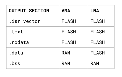
If we translate this table to linker scripting language:
SECTIONS
{
  /* The startup code goes first into FLASH */
  .isr_vector :
  {
    . = ALIGN(4);
    KEEP(*(.isr_vector)) /* Startup code */
    . = ALIGN(4);
  } >FLASH

  /* The program code and other data goes into FLASH */
  .text :
  {
    . = ALIGN(4);
    *(.text)           /* .text sections (code) */
    *(.text*)          /* .text* sections (code) */
    *(.glue_7)         /* glue arm to thumb code */
    *(.glue_7t)        /* glue thumb to arm code */
    *(.eh_frame)

    KEEP (*(.init))
    KEEP (*(.fini))

    . = ALIGN(4);
    _etext = .;        /* define a global symbols at end of code */
  } >FLASH

  /* Constant data goes into FLASH */
  .rodata :
  {
    . = ALIGN(4);
    *(.rodata)         /* .rodata sections (constants, strings, etc.) */
    *(.rodata*)        /* .rodata* sections (constants, strings, etc.) */
    . = ALIGN(4);
  } >FLASH

    /* used by the startup to initialize data */
  _sidata = LOADADDR(.data);

  /* Initialized data sections goes into RAM, load LMA copy after code */
  .data :
  {
    . = ALIGN(4);
    _sdata = .;        /* create a global symbol at data start */
    *(.data)           /* .data sections */
    *(.data*)          /* .data* sections */

    . = ALIGN(4);
    _edata = .;        /* define a global symbol at data end */
  } >RAM AT> FLASH


  /* Uninitialized data section */
  . = ALIGN(4);
  .bss :
  {
    /* This is used by the startup in order to initialize the .bss secion */
    _sbss = .;         /* define a global symbol at bss start */
    __bss_start__ = _sbss;
    *(.bss)
    *(.bss*)
    *(COMMON)

    . = ALIGN(4);
    _ebss = .;         /* define a global symbol at bss end */
    __bss_end__ = _ebss;
  } >RAM

}
Things to note:
.: is the location counter, and always refers to a location in an output sectionsymbol = expression: assign expression to this symbolALIGN(exp): Return the location counter (.) aligned to the nextexpboundary.expmust be an expression whose value is a power of two.>RAM AT> FLASH: The linker will normally set the LMA equal to the VMA. You can change that by using theATkeyword. The expression lma that follows the AT keyword specifies the load address of the section*(pattern):*is a wildcard pattern. For example:*(.text)means put here all the .text sections.KEEP(symbol): is a command keeps the symbol, when link-time garbage collection--gc-sectionsis in use
In conclusion, the job of the linker can be summarized as follows:
Final words
If there are files such as STM32F746NGHx_FLASH.ld, why should I bother to learn linker scripting language?
- Understanding linkers will help you to manage different input object files from different sources (C, ADA, assembler) into a single executable file.
- Understanding linking will help you understand some computers works, how the code is run.
I hope this guide is helpful ;)