Understanding STM32F7xx GPIOs
March 18, 2019
I’m using a discovery board based on STM32F74XX microcontroller, and in this post I’ll explain the how GPIOs works and how to configure them using C code.
Electrical diagram
A general purpose Input/Output pin has the following structure when is configured as an input and as an output.
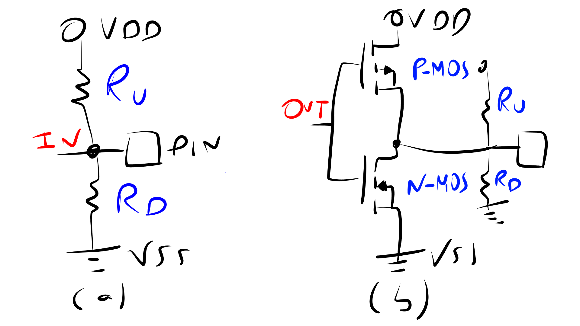
(a) Input: IN is the signal from the microprocessor, Ru is the pull-up resistor, Rd is the pull-down resistor.
(b) Output: OUT is the signal from the microprocessor, which goes to two enhancement MOSFETs (P-MOS and N-MOS).
The I/O pins can have several states:
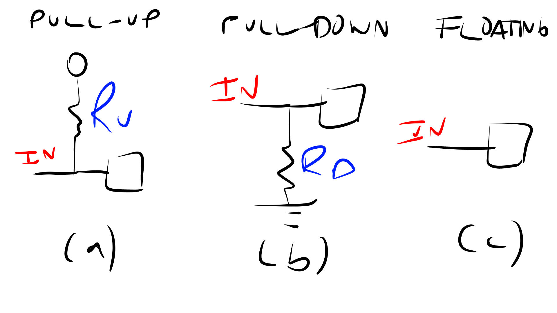
- Input:
- Pull-up: in this mode the input voltage of the pin is fixed to VCC or 1 when there is no input signal
- Pull-down: in this mode the input voltage of the pin is fixed to VSS or 0 when there is no input signal
- Floating: in this mode the value of the input is undefined when there is no input signal because the pin is floating.
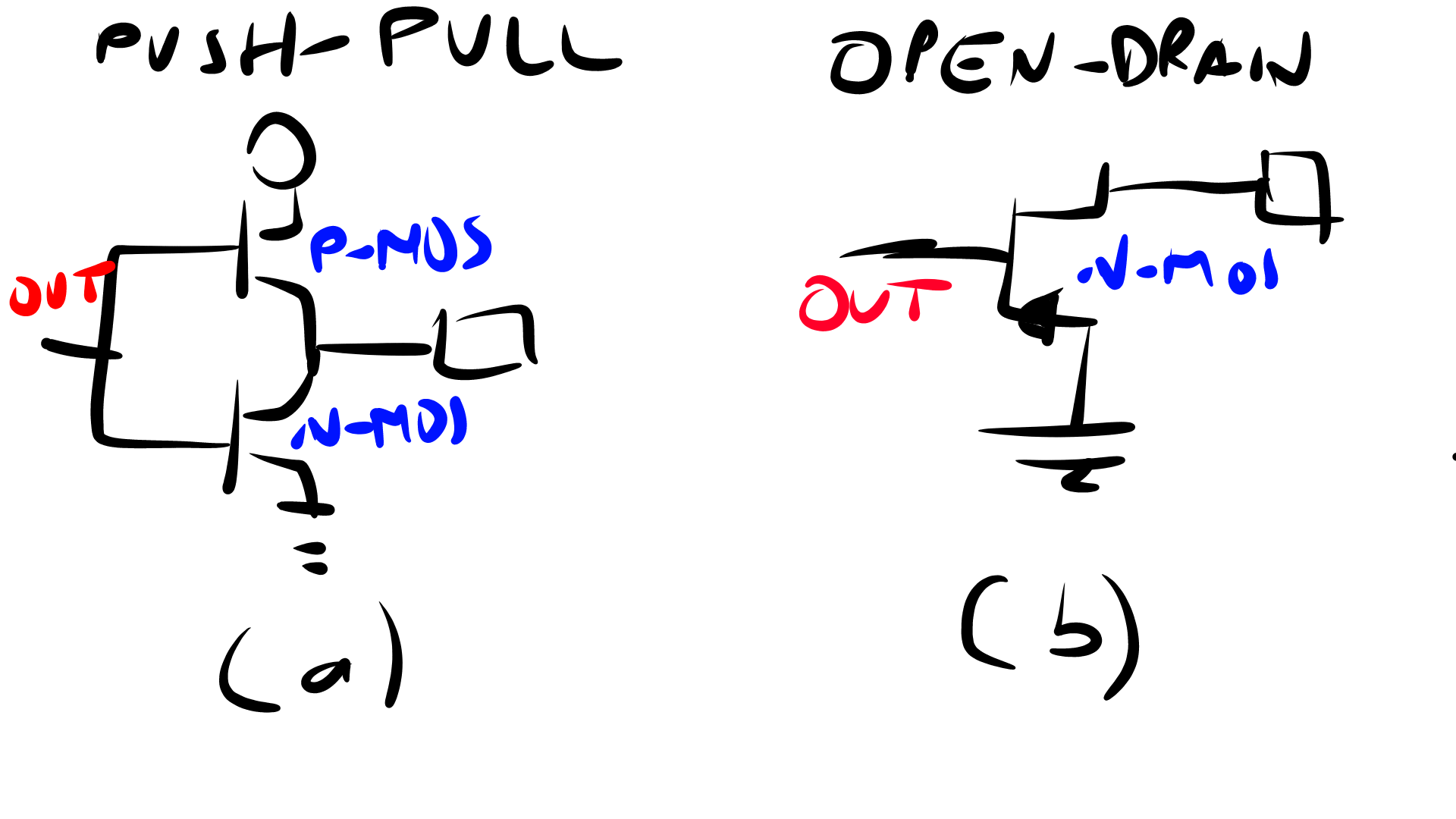
- Output:
- push-pull: is the normal or most common state, in this state the output can be VCC / 1 when OUT is 0, or VSS/0 when OUT is 1. NOTE: Usually there is an inversor before the MOSFETs, so if output pin value is 1 then the output can be also VCC/1.
- open-drain: this state is similar to the floating state when the pin is configured as input. When OUT is 1 the pin is floating or the drain pin of the MOSFET is open, and when OUT is 0 the pin is VSS
More detailed information in this application note AN4899: STM32 GPIO configuration for hardware settings and low-power consumption.
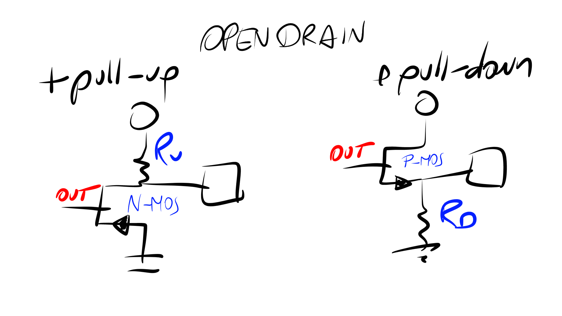
Also, when the output is in open-drain state, it can be combined with pull-up/down resistors in order to have a fixed output voltage when MOSFET is not activated.
There are two more possible configurations: Analog and Alternate function, but I didn’t read about it. Sorry folks.
STM32F7 GPIO Registers
Each general purpose I/O pin has
-
Four 32-bit configuration registers:
GPIOx_MODERor Mode register: input, output, alternate function or analogGPIOx_OTYPERor Output type register: push-pull or open-drainGPIOx_OSPEEDRor Output speed register: Low, Medium, High and Very high speedGPIOx_PUPDRor Pull-up/Pull-down register: No pull-up/down, pull-up or pull-down
-
Two 32-bit data registers:
GPIOx_IDR: Input data registerGPIOx_ODR: Output data register
- A 32-bit set/reset register
GPIOx_BSRR - A 32-bit locking register
GPIOx_LCKR - Two 32-bit alternate function
where x can be from A to K.
GPIO basic configuration
In order to configure our GPIO I need basically to set up the configuration registers. Here is a table that summarizes the port configuration for just one pin:
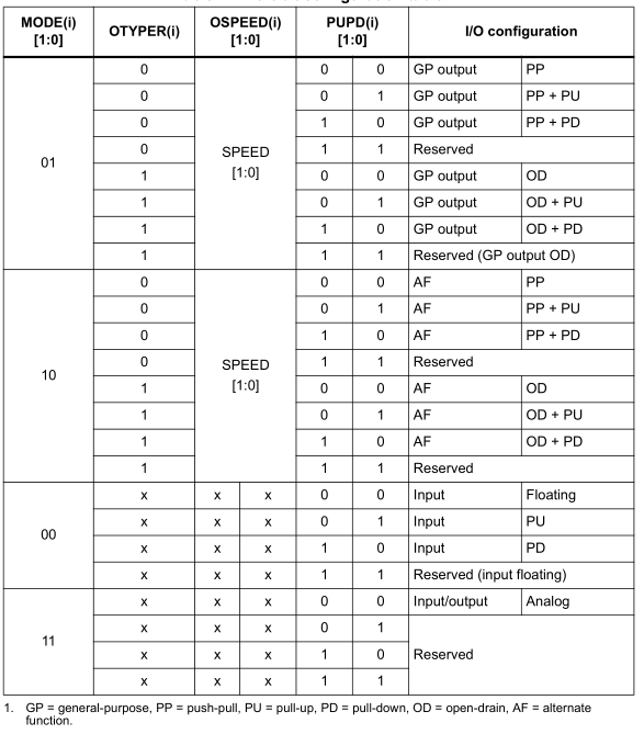
Note: Each port (A to K) has 16 pins pyy (yy from 00 to 15), so in the following section we will focus only on the number of bits needed for each pin to setup the registers.
GPIO port mode register (GPIOx_MODER)
Each pin pyy needs 2-bits for mode, so GPIOx_MODER register could be seen as follows:
 -------------------------------
 | p15 | p14 | ... | p01 | p00 |
 -------------------------------
       |     |     |     |     |
       30    28    04    02    00
where pyy can have the following values:
00: input mode01: output mode10: alternate function mode11: analog mode
As an extra note, some ports have a reset value different from 0x0000 0000
0xA800 0000for port A0x0000 0280for port B
GPIO port output type register (GPIOx_OTYPER)
Each pin pyy only needs 1-bit for type, so GPIOx_OTYPER register could be seen as follows:
 ----------------------------------------------
 |   RESERVED   | p15 | p14 | ... | p01 | p00 |
 ----------------------------------------------
                      |     |     |     |     |
                      15    14    02    01    00
where pyy can have the following values:
0: Output push-pull1: Output open-drain
The RESERVED bits (31:16) must be kept at 0x0000
GPIO port output speed register (GPIOx_OSPEEDR)
Each pin uses 2 bits for speed, so GPIOx_OSPEEDR register could be seen as follows:
 -------------------------------
 | p15 | p14 | ... | p01 | p00 |
 -------------------------------
       |     |     |     |     |
       30    28    04    02    00
where pyy can have the following values:
00: low speed (up to 3MHz)01: medium speed (up to 50MHz)10: high speed (up to 100MHz)11: very high speed (up to 180MHz)
The values of speed will depends on the microcontroller, load and VCC. Thus, check the datasheet for your microcontroller, in my case the values are shown above.
As an extra note, some ports have a reset value different from 0x0000 0000
0x0C00 0000for port A0x0000 00C0for port B
GPIO port pull-up/pull-down register (GPIOx_PUPDR)
Each pin uses 2 bits for set up internal resistors, so GPIOx_PUPDR register could be seen as follows:
 -------------------------------
 | p15 | p14 | ... | p01 | p00 |
 -------------------------------
       |     |     |     |     |
       30    28    04    02    00
where pyy can have the following values:
00: no pull-up/down01: pull-up10: pull-down11: Reserved
As an extra note, some ports have a reset value different from 0x0000 0000
0x6400 0000for port A0x0000 0100for port B
Summary
I have described the basic concepts about GPIO in STM32F74XX ARM-based microcontrollers. All these concepts were somehow overwhelmed to me, but I hope this post helped you to understand how GPIOs works, and how to set them up.
Cheers!