How do microcontrollers load an application?
April 3, 2019
I was learning about how to program microcontrollers in C and I wasn’t aware about the importance of startup files, vector tables and the linker. Basically, this three concepts are needed in order to understand how a microcontroller run an application. I already explained the linker script in a previous post. I recommend to read that post before, in order to understand the next concepts.
C Runtime environment and startup file
C assumes that heap and stack are already defined, and also that there is a main function (check Hacking function main)
Thus, one should setup the C run time environment in order to run an application, and the startup file is the way to go.
It’s usually written in assembly because it’s hardware dependent.
This startup file must do at least the following:
- Copy values from Flash to RAM (
.data) - Clear uninitialized RAM (
.bss) - Call the
mainfunction
The following code is an example of a startup file:
// Copyright William Ransohoff, Vivonomicon, LLC, 2017

.syntax unified
.cpu cortex-m0
.fpu softvfp
.thumb

// Global values.
.global reset_handler

//
// The Reset handler. Called on reset.
//

.type reset_handler, %function
reset_handler:
  // Set the stack pointer to the end of the stack.
  // The '_estack' value is defined in our linker script.
  LDR  r0, =_estack
  MOV  sp, r0

  // Copy data from flash to RAM data init section.
  // R2 will store our progress along the sidata section.
  MOVS r0, #0
  // Load the start/end addresses of the data section,
  // and the start of the data init section.
  LDR  r1, =_sdata
  LDR  r2, =_edata
  LDR  r3, =_sidata
  B    copy_sidata_loop

  copy_sidata:
    // Offset the data init section by our copy progress.
    LDR  r4, [r3, r0]
    // Copy the current word into data, and increment.
    STR  r4, [r1, r0]
    ADDS r0, r0, #4

  copy_sidata_loop:
    // Unless we've copied the whole data section, copy the
    // next word from sidata->data.
    ADDS r4, r0, r1
    CMP  r4, r2
    BCC  copy_sidata

  // Once we are done copying the data section into RAM,
  // move on to filling the BSS section with 0s.
  MOVS r0, #0
  LDR  r1, =_sbss
  LDR  r2, =_ebss
  B    reset_bss_loop

  // Zero out the BSS segment.
  reset_bss:
    // Store a 0 and increment by a word.
    STR  r0, [r1]
    ADDS r1, r1, #4

  reset_bss_loop:
    // We'll use R1 to count progress here; if we aren't
    // done, reset the next word and increment.
    CMP  r1, r2
    BCC  reset_bss

  // Branch to the 'main' method.
  B    main
.size reset_handler, .-reset_handler
The reset_handler section must be defined as ENTRY_POINT in the linker in order to work as startup point.
Vector Table
The vector table contains the reset value of the stack pointer, and the start addresses for all exception handlers including the reset handler. The vector table is described in detail in each microcontroller reference manual, and it’s usually given by the vendor, but you can also write your own, you just only be aware of the addresses.
An snapshot of the vector table for the microcontroller STM32F0 is shown below:
.syntax unified
.cpu cortex-m0
.fpu softvfp
.thumb

.global vtable
.global default_interrupt_handler

//  The vector table.

.type vtable, %object
.section .vector_table,"a",%progbits
vtable:
    .word _estack
    .word reset_handler
    .word NMI_handler
    .word hard_fault_handler
    .word 0
    .word 0
    .word 0
    .word 0
    .word 0
    .word 0
    .word 0
    .word SVC_handler
    .word 0
    .word 0
    .word pending_SV_handler
    .word SysTick_handler
    // 16-31
    .word window_watchdog_IRQ_handler
    .word PVD_IRQ_handler
...
Note that .word means that the vector is 16-bits long.
Example
I will show parts of an ELF file disassembly based on a C code for STM32F0 microcontrollers:
main.elf:     file format elf32-littlearm

Disassembly of section .vector_table:

08000000 <vtable>:
 8000000:	20001000 	andcs	r1, r0, r0
 8000004:	080000c5 	stmdaeq	r0, {r0, r2, r6, r7}
 ...

Disassembly of section .text:

80000c4 <reset_handler>:
 80000c4: ldr	r0, [pc, #40]	; (80000f0 <reset_bss_loop+0x6>)
 80000c6: mov	sp, r0
 80000c8: movs	r0, #0
 80000ca: ldr	r1, [pc, #40]	; (80000f4 <reset_bss_loop+0xa>)
 80000cc: ldr	r2, [pc, #40]	; (80000f8 <reset_bss_loop+0xe>)
 80000ce: ldr	r3, [pc, #44]	; (80000fc <reset_bss_loop+0x12>)
 80000d0: b.n	80000d8 <copy_sidata_loop>

080000d8 <copy_sidata_loop>:
 ...
 80000e4: b.n	80000ea <reset_bss_loop>
 ...


080000ea <reset_bss_loop>:
 ...
 80000ee: b.n	8000108 <main>
 ...


08000108 <main>:
...

Disassembly of section .dynamic_allocations:

20000004 <_ssystem_ram>:
Things to notice:
- STACK POINTER is
0x2000 1000, and defined at the beginning ofvtable - PROGRAM COUNTER is
0x0800 00c5, in reality is0x0800 00c4but the least-significant bit should be 1, indicating that the code in that section is written in Thumb code. Check vector table snapshot above. - HEAP starts at
0x2000 0000because it’s a 4KB SRAM memory. Remember that HEAP is for dynamic memory allocations such asmallocorcalloc - The start up program jumps from
reset_handlertocopy_sidata_looptoreset_bss_loopand tomain.
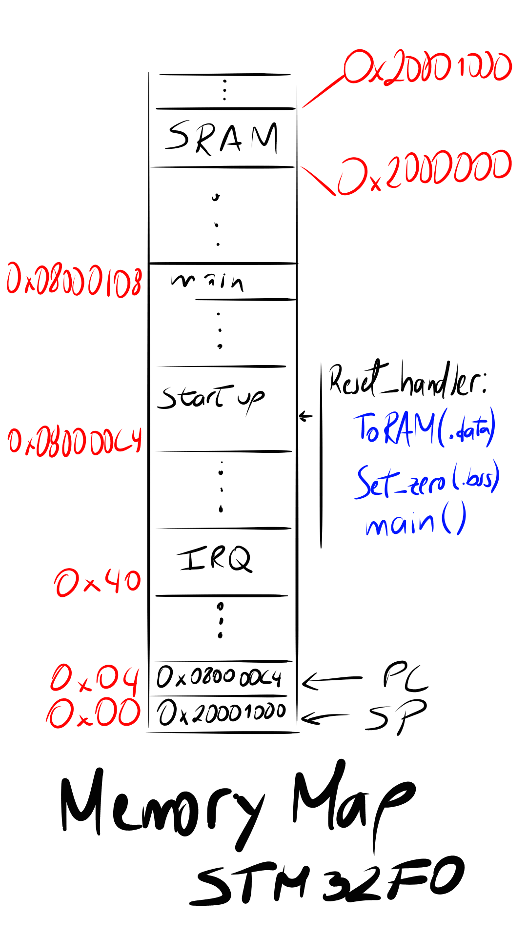
A picture of the memory map is shown below:
Final words
I have presented the basic concepts you should know in order to understand how your C code will be executed in the microcontroller. I hope you learned as much as I did.